


What separates an ordinary machined component from a precision-engineered gear? Often, the difference comes down to the details that are easy to overlook: the accuracy of the tooth profile, the consistency of the machining process, and the cutting tool selected for the job.
For manufacturers across the United States, these details have a direct impact on production quality, equipment reliability, and operating costs. Whether a shop is producing specialized gear components for industrial machinery or manufacturing worm gearing for power transmission systems, the right tooling helps turn engineering specifications into dependable finished parts.
Two important tooling categories deserve particular attention: form milling cutters and worm gear cutting tools. Although they serve different purposes, both play a valuable role in producing gear-related components with the required geometry.
Understanding how these tools work, where they fit into the manufacturing process, and what to consider before selecting them can help manufacturers make smarter tooling decisions.
Why Gear-Cutting Precision Starts With the Tool
Gears may appear simple at first glance, but their performance depends on carefully controlled geometry. Tooth spacing, profile accuracy, surface condition, and alignment all influence how components engage and transmit motion.
When the cutting process falls short, manufacturers may encounter inconsistent dimensions, excessive noise, vibration, premature wear, or rejected parts. These problems can increase production costs and interrupt delivery schedules.
Selecting appropriate cutting tools helps manufacturers work toward:
- Consistent tooth profiles and dimensions
- Better control over machining operations
- Reduced risk of avoidable rework
- More predictable tool wear and maintenance
- Reliable results across production batches
However, tool selection alone cannot guarantee quality. Machine capability, workpiece material, setup accuracy, cutting parameters, and inspection procedures must all work together.
Form Milling Cutters: Shaping the Details That Matter
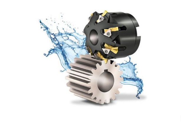
A form milling cutter is designed with a cutting profile suited to a particular shape. As the cutter engages the workpiece, its geometry helps produce the corresponding feature in the material.
In gear manufacturing, suitable form milling cutters can be used to machine tooth spaces and other specified profiles. The cutter must be selected according to the intended geometry, dimensions, and machining requirements.
Unlike gear-generating processes that develop the tooth profile through coordinated tool and workpiece motion, conventional form milling relies more directly on the cutter’s profile. This makes cutter selection and workpiece indexing particularly important.
How Do Form Milling Cutters Work?
The process begins with securely mounting the workpiece and positioning the cutter according to the machining plan. The rotating cutter removes material to create the required profile. For gears produced through conventional indexed form milling, the workpiece is repositioned between cuts to machine successive tooth spaces.
The accuracy of the finished component depends on several factors:
- Cutter profile: The cutting geometry must be appropriate for the intended feature.
- Indexing accuracy: Tooth spaces must be positioned correctly relative to one another.
- Machine rigidity: Movement or vibration can affect dimensional consistency.
- Workholding: Secure positioning helps maintain alignment during machining.
- Tool condition: Worn or damaged cutting edges can compromise the finished surface.
When these factors are controlled, form milling can be a useful option for selected gear profiles and specialized machining requirements.
Where Can Form Milling Cutters Be Useful?
Form milling cutters may be suitable for a range of applications, depending on cutter design and machine capability.
Examples include:
- Producing selected spur gear tooth spaces
- Machining specialized profiles and features
- Manufacturing certain low-volume or custom components
- Supporting prototype and development work
- Producing components where a form-based milling process is appropriate
The best application depends on the gear design and required tolerances. Form milling is not automatically the most economical approach for every gear, especially when production volume, profile complexity, or accuracy requirements favor a generating process.
For manufacturers, the important question is whether the cutter and machining method can produce the required geometry consistently within the available production constraints.
Worm Gear Cutting Tools: Precision for Motion and Power Transmission
Worm gearing provides a practical solution for many mechanical systems that need a particular speed relationship or compact arrangement. A typical worm gear set consists of a screw-like worm that meshes with a worm wheel.
These systems are found in various industrial applications, including selected gearboxes, conveying equipment, positioning mechanisms, and machinery used in manufacturing facilities.
Producing reliable worm gearing requires attention to the geometry of both mating components. The teeth must interact as intended, and the manufacturing process must account for the design requirements rather than treating the worm and worm wheel as interchangeable gear forms.
What Makes Worm Gear Cutting Different?
Worm gear manufacturing can involve specialized machining methods and tooling selected for the geometry of the worm or worm wheel.
The process depends on the component being produced. A worm shaft and a worm wheel have different geometries, so the appropriate cutting method and tool design may differ as well.
For this reason, worm gear cutting tools should be selected only after confirming the component drawing, required tooth form, material, and machine setup.
Depending on the design and manufacturing method, relevant tooling may include suitable hobs, milling cutters, or other specialized cutting tools. Not every tool used for conventional spur gears is suitable for worm gearing.
Applications That Depend on Worm Gearing
Worm gear systems are used in situations where their mechanical characteristics suit the equipment’s requirements. Common examples include:
- Industrial speed-reduction systems
- Material-handling and conveying equipment
- Adjustment and positioning mechanisms
- Selected packaging and processing machinery
- Specialized mechanical drive assemblies
Actual suitability depends on the design, operating conditions, load requirements, lubrication, and other system-level factors. Tooling selection is one part of producing a component that performs as intended in its application.
What Should Manufacturers Check Before Selecting Worm Gear Cutting Tools?
Start with the engineering drawing. Confirm the gear arrangement, dimensions, tooth geometry, tolerances, and material specifications.
Next, evaluate the available machine and manufacturing process. A tool that is appropriate for one worm gear design may not be suitable for another. The cutting strategy must match the intended geometry and the machine’s capabilities.
Finally, establish how the finished components will be inspected. Depending on the drawing and application, checks may include dimensional verification, tooth geometry, surface condition, and the fit or engagement of mating components.
This systematic approach reduces the risk of choosing tooling based on a broad product category rather than the actual manufacturing requirement.
Form Milling Cutters vs. Worm Gear Cutting Tools
Although these categories can overlap in certain tooling applications, they describe different aspects of the manufacturing process. Form milling cutters are defined largely by their profile-based cutting approach, while worm gear cutting tools are selected for the specialized geometry and requirements of worm gearing.
| Factor | Form Milling Cutters | Worm Gear Cutting Tools |
| Primary consideration | Producing a specified profile through milling | Producing the required geometry for worm gearing |
| Tool selection | Based on profile, dimensions, and machining method | Based on worm or worm-wheel design and manufacturing process |
| Process priorities | Cutter profile, indexing, workholding, and alignment | Gear geometry, tool compatibility, machine setup, and component engagement |
| Potential applications | Selected gear tooth spaces and specialized profiles | Worm shafts, worm wheels, and related gearing components |
| Key question | Can the cutter accurately produce the required profile? | Is the tool suitable for the specific worm gear component? |
The two categories should not be treated as competing alternatives in every situation. The correct choice depends on the component, the required machining operation, and the production objectives.
Five Factors to Consider When Choosing Gear-Cutting Tools
For U.S. manufacturers, an effective tooling decision should balance technical requirements with practical production needs.
1. Define the Required Geometry
Review the engineering drawing before ordering a cutter. Identify the gear type, tooth dimensions, profile requirements, tolerances, and any specified surface-finish criteria.
Clear specifications help establish whether a form milling approach or specialized worm gear tooling is appropriate.
2. Understand the Workpiece Material
Material properties influence machining behavior, cutting forces, tool wear, and the selection of cutting parameters.
Manufacturers should identify the material grade and relevant condition, including any heat treatment that affects machining. Tooling recommendations should be based on the actual material rather than assumptions.
3. Confirm Machine Compatibility
Check that the machine can accommodate the selected tool and perform the required movements accurately.
For form milling, this includes cutter mounting, workpiece positioning, and indexing. For worm gear components, the machine and tool must be suitable for the specific manufacturing method and component geometry.
4. Evaluate Production Volume
A tool that works well for a prototype may not be the most cost-effective solution for recurring, high-volume production.
Compare setup requirements, cycle time, tooling costs, expected tool life, and inspection needs. The goal is to evaluate the total manufacturing process rather than focusing on the initial cutter price alone.
5. Establish Tool Maintenance and Inspection Practices
Regular tool inspection helps identify wear, chipping, or damage before these conditions affect production quality.
Manufacturers should also verify finished parts against the specified drawing requirements. Depending on the application, this may involve checking dimensions, tooth spacing, profile accuracy, and other critical characteristics.
A consistent inspection routine provides useful feedback about both tooling condition and process stability.
Common Tooling Mistakes and How to Avoid Them
Even well-equipped manufacturing facilities can experience problems when important details are overlooked.
Choosing a cutter by name alone: Similar tool categories can serve different purposes. Confirm the required geometry and machining method first.
Ignoring setup accuracy: Incorrect positioning or indexing can create errors that cannot be corrected simply by changing cutting parameters.
Overlooking tool wear: Continuing to use a damaged or excessively worn cutter can increase variation and rework.
Focusing only on purchase price: Tool cost should be evaluated alongside tool life, productivity, setup time, and finished-part quality.
Skipping final verification: A completed machining cycle does not automatically mean the component meets its specifications. Inspection remains essential.
Avoiding these mistakes helps manufacturers create a more predictable production process and make better use of their tooling investment.
Building Confidence Into Every Machining Operation
Precision manufacturing is not about selecting the most expensive tool or following the same process for every component. It is about understanding what the part requires and choosing a machining approach that can deliver those results consistently.
Form milling cutters offer a profile-based method for suitable machining applications, while worm gear cutting tools address the specialized requirements of worm gearing. Both require careful consideration of geometry, material, machine capability, and inspection.
For manufacturers across the USA, this attention to detail can support better process control, more consistent components, and fewer avoidable production problems.
Explore Gear Tooling Solutions With SS Tools
Choosing suitable tooling starts with a clear understanding of the part being manufactured. Component drawings, material specifications, machine details, and required tolerances provide a strong foundation for evaluating the available options.
SS Tools can be a starting point for exploring gear-tooling requirements and identifying the information needed for a productive tooling discussion.
When every tooth matters, the right decision begins with the right technical details. By matching the cutting tool to the application and maintaining consistent process controls, manufacturers can take a more confident approach to precision gear production.